Looking at the LPC810 UART
Posted at 2015-05-07.
I was looking through some articles I've missed on the jeelabs blog. Seems embello. has got some interesting updates as well, so I pulled that.
I thought I'd log some notes.
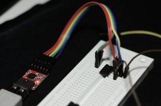
It seems that the ISP uses
pin 8 (PIO0_0) for RX,
pin 2 (PIO0_4) for TX,
probably pin 1 for RESET,
and pin 5 to enter the bootloader.
Pins 6 and 7 are power and ground.
I didn't yet look up confirmation if pins 1&5 could be easily connected to the ISP, but using 8&2 for UART in any applications seems like an attractive default. The LPC810 doesn't have too many output options because of its pin count so shared ISP and UART pins would seem useful.
Serial output post contains interesting links and information.
The little sample says
LPC_SWM->PINASSIGN0 = 0xFFFFFF04UL;
Other demos refer to
sys.h
and it has, in Serial.init(),
LPC_SWM->PINASSIGN[0] = 0xFFFF0004;
Looking at the huge
LPC810 UM pdf,
PINASSIGN0 contains the pin assignments for uart0.
Lowest byte sets TX (to 04 in both examples).
Next lowest sets RX (to 00 in sys.h).
The two next bytes would set RTS/CTS.
I didn't notice it mentioned, but I presume setting a value over 0x11
will set the pin nowhere.
Default values are all set to 0xFF.
Part 9.3 predicts SWD should be turned off by these choices without problem.
The boot loader assigns the SWD functions to pins PIO0_2 and PIO0_3. If
the user code disables the SWD functions through the switch matrix to
use the pins for other functions, the SWD port is disabled.
I noticed that much of the sources have non-evil licenses and could be useful. The whole embello repository contains a lot of useful stuff for LPC8xx, and Jeelabs is a wonderful resource.
Links
- My main LPC page
- Got LPC810 chips blog post
- João Vilaça's lpc810 pages with very nice pin table
- Lpc21isp
- Flushmagic also seems to recognize the chip.
