Got ESP201 modules
Posted at 2015-06-04.
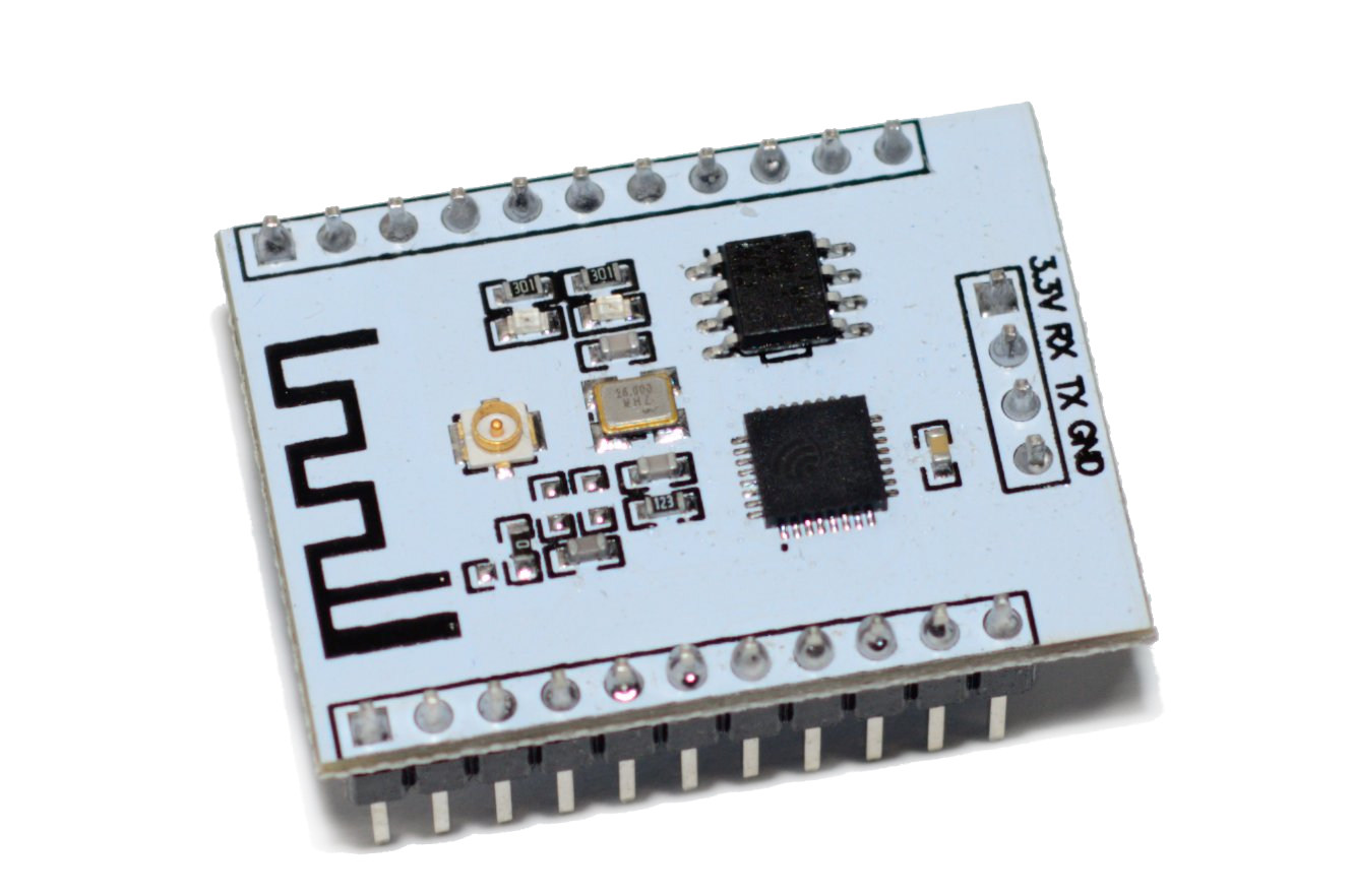
I got these neat little boards with ESP8266. This is one of many types and usually goes by the name of ESP201.
Apparently some ESP201 modules have antenna connectors backwards and shorted The antenna connector is soldered on correctly in mine.
It should be quite easy to wire up a little motherboard for this with power (maybe battery), switches, and whatever IO or connectors are needed. I also have a display I'd like to try.
The footprint is small enough to mount on the smallest Dirty PCB for a compact, cheap, and cheerful package!
Wiring up
I followed some guides and poked around. It seemed all I could get out at any rate was garbage, like the bitrate was wrong. I mentioned this on #helsinkihacklab and got some suggestions. Eventually the important bit was pulling down IO15. Then, garbage was followed by the magic word "ready".
First, your board might talk at any of several baud rates. The ones to try first are 9600 and 115200. Then 57600 and/or 76800 (38400 * 2). Note the noise when you reset the device (pull the RST pin to ground) is typically some bootup messages at 76800. But there should be a ”ready“ message at the selected baud rate if your UART Rx is wired correctly. - esp8266 wiki
I went with my usual CP2104 and 115200, 8N1 indeed works in my usual picocom and ipython use.
The ESP-8266 is a WIFI device and can draw significant amounts of current (over 200 mA). -- GregM
I tested with a LM1117 based regulator and haven't stressed the device, measured it, or noticed anything odd.
Terminal session
AT

OK
AT+RST

OK

 ets Jan  8 2013,rst cause:4, boot mode:(3,6)

wdt reset
load 0x40100000, len 212, room 16
tail 4
chksum 0x5e
load 0x3ffe8000, len 788, room 4
tail 0
chksum 0x1c
load 0x3ffe8314, len 72, room 8
tail 0
chksum 0x55
csum 0x55
jump to user1

ready
AT+GMR
00170901

OK

AT+CWMODE=3
Another reset, as suggested...
AT+CWJAP?
+CWJAP:""

OK
AT+CWLAP
+CWLAP:(0,"",0,xx:xx:xx:xx:00:00,0)
+CWLAP:(3,"somename",-83,xx:xx:xx:xx:5d:80,1)
<...>

OK

OK
AT+CWJAP="myownlan","somepassword"

OK
AT+CWJAP?
+CWJAP:"myownlan"

OK
AT+CIFSR
10.555.666.777
Some details changed, obviously. But it seems to connect and shows up in router interface with a -69 dBm signal. Neat.
No 5 GHz networks in that list as far as I know.
Antenna
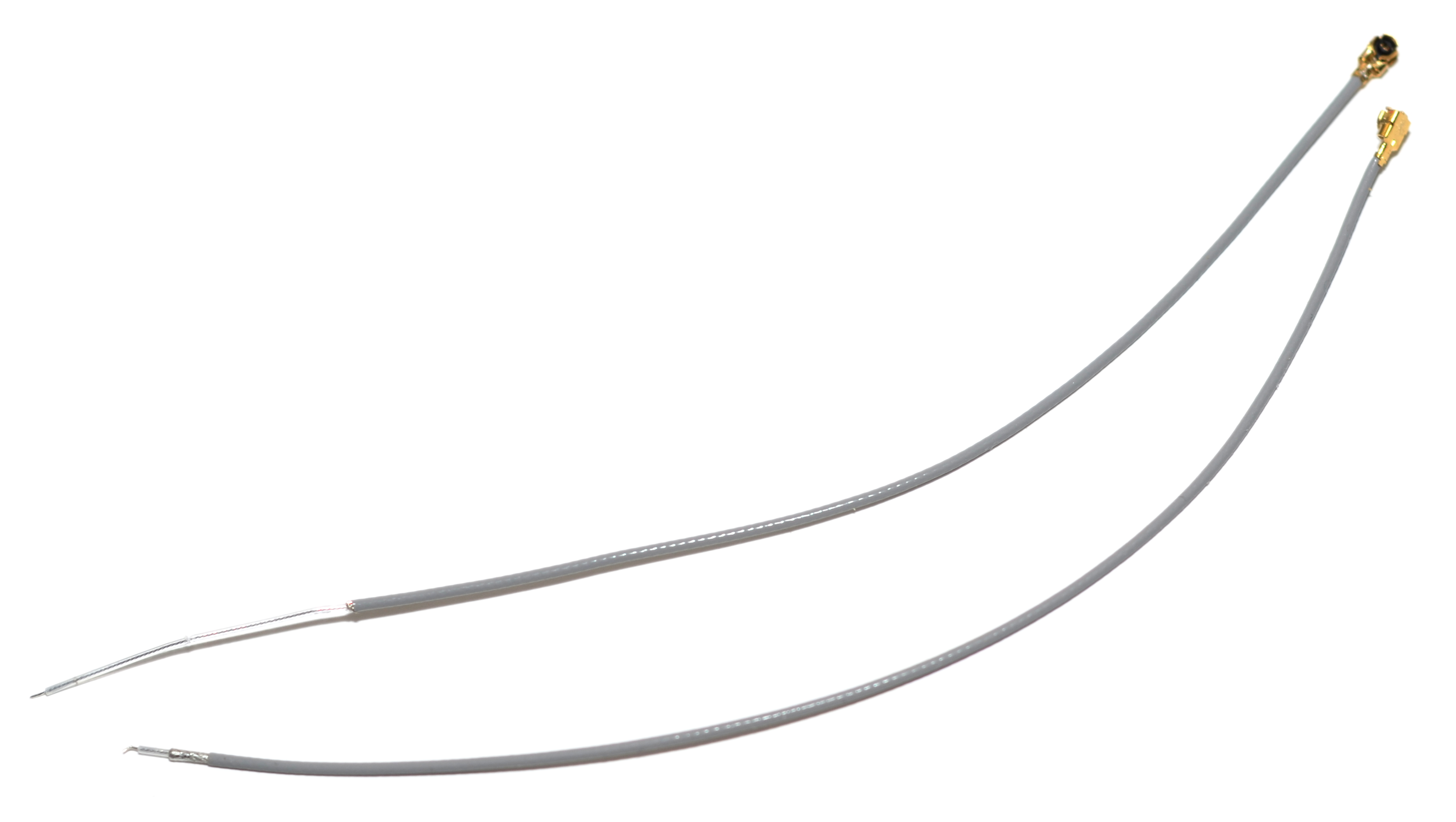
There is a jumper (0R) that can be soldered two ways to select the pcb antenna or the connector. This model, like others I've seen in articles, came wired for external antenna. There was also a wire antenna with a suspiciously short stripped section.
I bought the same module and found out it had very low signal intensity as you said. In my case the pigtail antenna was the problem. The core wire was sticking out of the shield around it by a few mm only. Physics says that for a lambda/4 antenna at 2.4 Ghz the central wire needs to be about 31 mm longer than the shield. I just removed enough of the shield/mesh to match this difference in length. I left the tubular insulating layer around the central wire to prevent any shortage. With that change the signal strength as shown with AT+CWLAP went up from about -70 to about -35 dB. This is a similar to the ESP8266-01 I have as well. -- Bernd Pennemann
There is a picture of a more stripped antenna in this antenna troubleshooting post.
I have two, so it ought to be easy to A/B test different antennas. Alternatively, it might be possible to adapt the wire as a wire and use some completely different design.
- No antenna gets to -72 dBm.
- Second wire stripped to 15.5 mm yields -70 dBm.
- Stripping further to 31 mm yields -61 dBm. (4/5 bars on the graph)
- An antenna from a dead laptop yields -64 dBm.
- Removing the antenna goes to -66 dBm.
- Put the 31 mm back in, and I see -61 dBm.
That looks disappointing at first but it's better than my phone and anyway, the router is in another room behind metal in a closet where the uplink lives. Noise floor in same stats is up at -81 dBm. There doesn't seem to be a very strong response to changes. This experiment might not be useful.
I noticed the AT+CWLAP output has a (probable) signal strength number. So, I repeated the tests.
- 31 mm strip yields -71 to my network
- No antenna yields -72
- Laptop antenna yields -71
- 4 mm strip yields -76
- No antenna yields -78
- 31 mm strip yields -71
The numbers are all over the place, but there seems to be some change to the averages. Having them jump 5 units in consecutive samples a few seconds apart doesn't inspire confidence.
Plans
Next step is probably trying to get the NodeMCU firmware on it.
Links
- esp8266 datasheet
- Quick start guide pdf
- ESP8266 troubleshooting at Vaasa Hacklab
- Getting started with the esp8266 at esp8266 wiki
- Antenna troubleshooting
- Sparkfun thread on esp8266
- Nurdspace page on esp8266 with good specs
- Schematic for some design
- Electrodragon on esp8266
- AT command set
- Design guide
- Micropython on esp8266
- iTead on esp8266 - NodeMCU - NodeMCU on Wikipedia
- Olimex IoT
- thread on ESP201, nice graphics
- ePanorama on ESP8266
- NodeMCU repo
- esptool
- picocom