Some metal projects
I've made a few little projects over time and even wrote a few notes on them. Today, I finally picked out a few photos and decided to pull some of them up into a post.
I'll hope to do a lot more of these soon.
I've been running a "new" motor on the taig lately and it seems to be working nicely.
Brass hammer
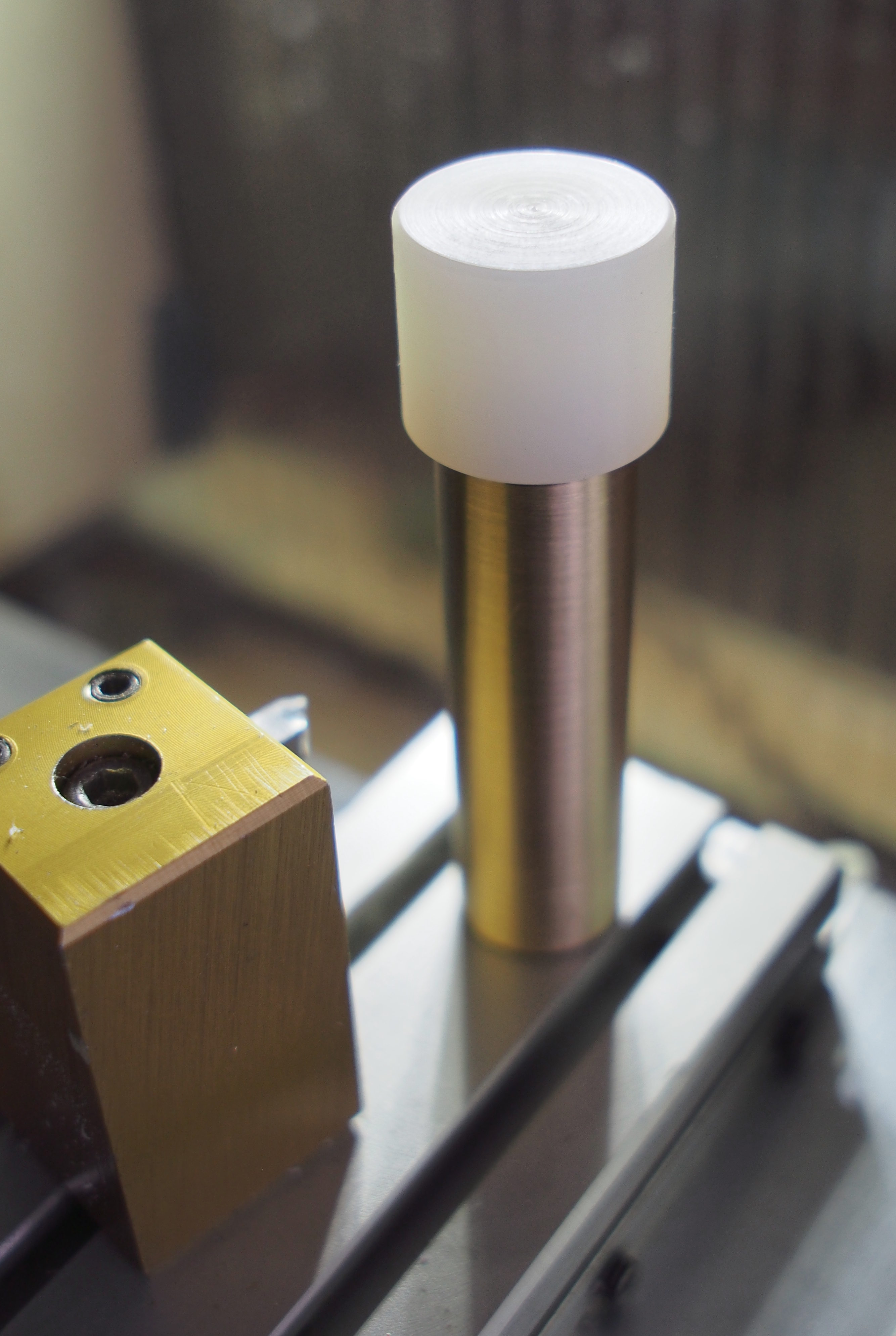
I can't seem to find a brass hammer in this town, so I thought I'd try making one. I bought some round scrap brass rod recently, so I weighed it and decided a piece might make a nice head.
I turned a bit of nylon down to make a cap for one end. Threading the brass to M12 was a minor nightmare and the result is not good, but doesn't really show once the cap is on. Tapping PA6 for M12 was no picnic either. Luckily the bulk of that can be bored, which works out very well.
Hammer head is done and is useful as is. I should still make a handle some day.
Clamping round stock
I made a little clamp from some Al scrap. It's about 15 x 25 x 25 mm rectangle with an 8 mm hole through off-center on a long side and a slit sawed in with some M4 screws to tighten.
I've used this quite a bit in holding stock while threading or doing something else that needs me to hold on to a smooth round part without marking it.
Unholy alliance
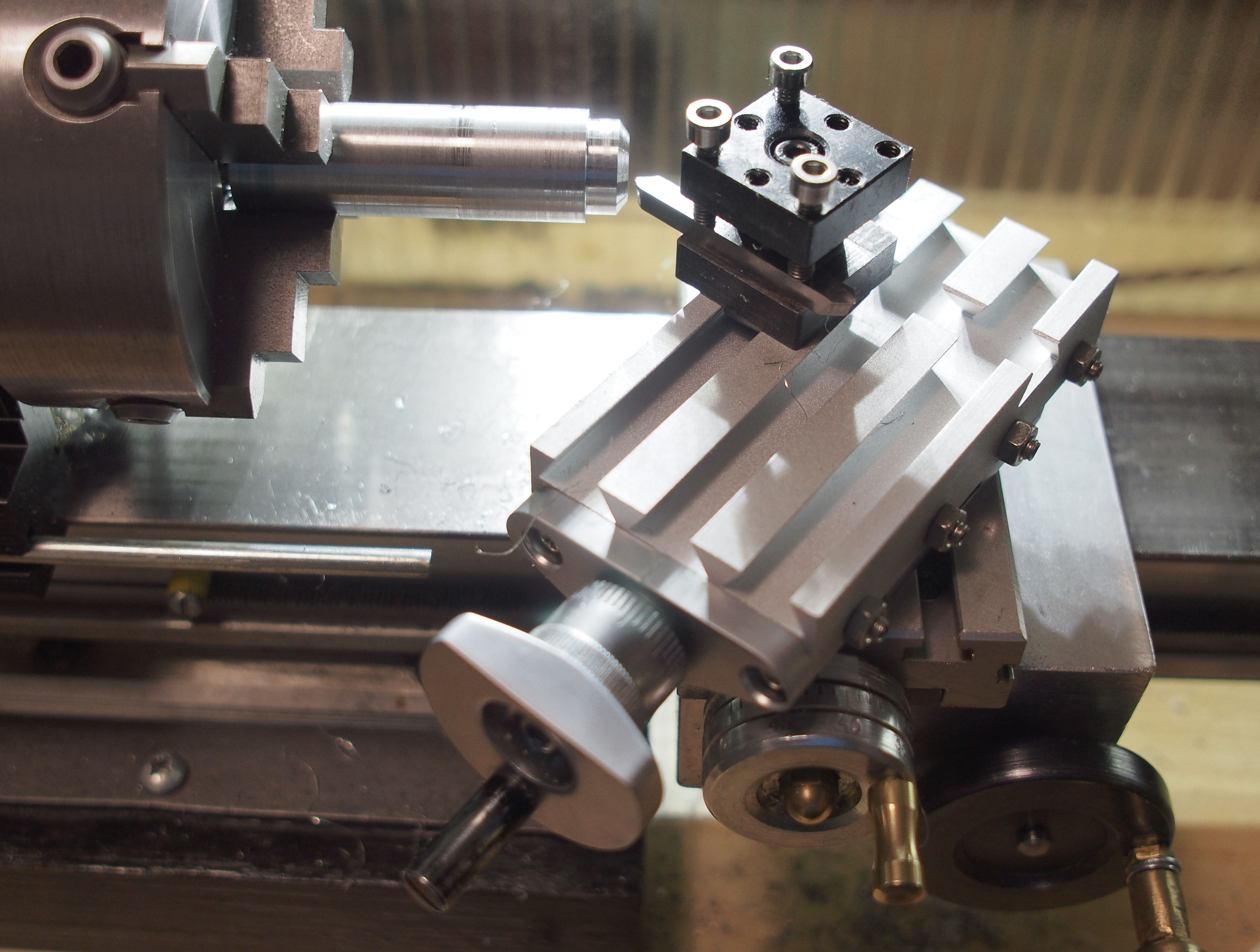
I couldn't resist trying this. A combination of finest American and Chinese craftsmanship (with some half-assed Finnish hackery thrown in). The topslide from the Unimat ML fits quite nicely on the Taig lathe. The toolpost and 4 mm tool even hit pretty close to center height without shims. Certainly close enough to turn this pretty nice cone in Al.
Given the location and size of mounting holes, there's not much room (if any) to set angles. So to really use this would possibly need some different way of attaching it. Now it's just stuck at roughly 55°.
I think with some angle or a straight angled block, this could even pretend to be a milling attachment. Not that I can mount a mill yet.
Rigidity probably shouldn't be impressive, but there's no noticeable wobble and feeding is quite smooth. Even the handwheels don't really interfere.
Originally I thought I'd just turn a piece of Al to make a riser for the toolholder to get it to Taig height and have a free second toolpost. I'll probably still do that someday.
Toolpost riser
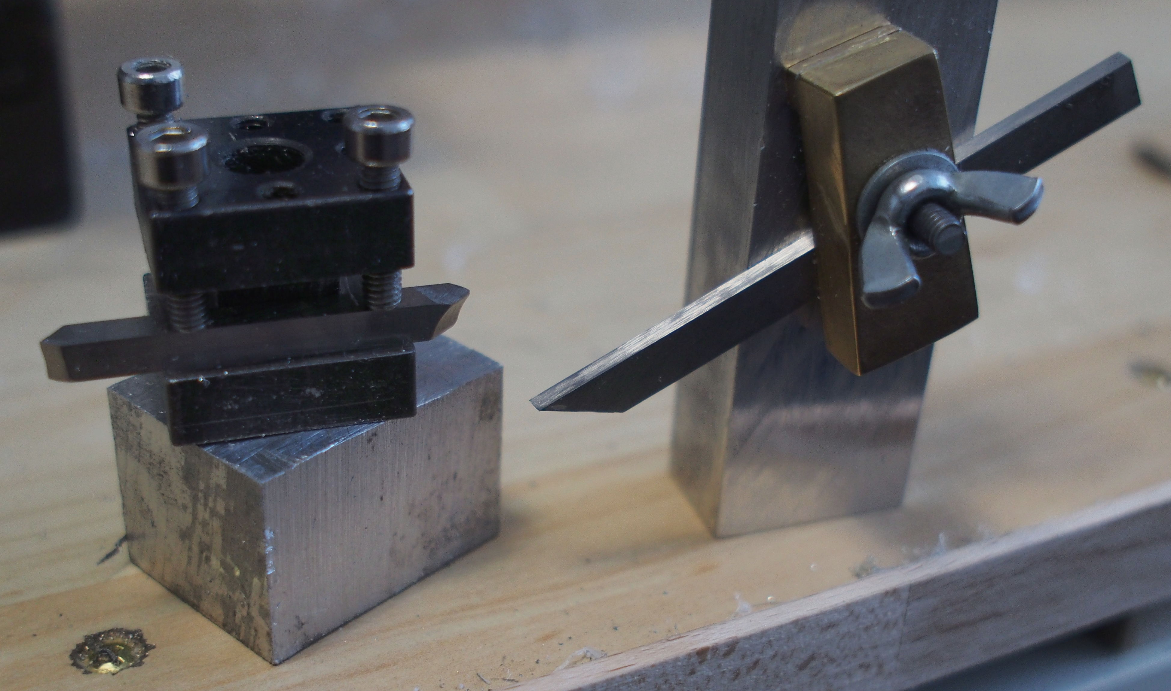
I did make the riser piece for the Unimat ML toolpost to raise it to Taig height.
This was a piece of Al faced all around and drilled off-center for the mounting bolt to pass through. I then used the mounting bolt hole to turn a recess for the toolpost that was somewhere between the width and diagonal of the toolpost footprint. I then marked the footprint and filed away the remaining corners and now the toolpost somewhat registers on the riser instead of spinning around freely thus making them hopefully rotate as a stable unit.
I'm missing a long enough bolt and a square nut to mount it, though.
Chunky carriage handle

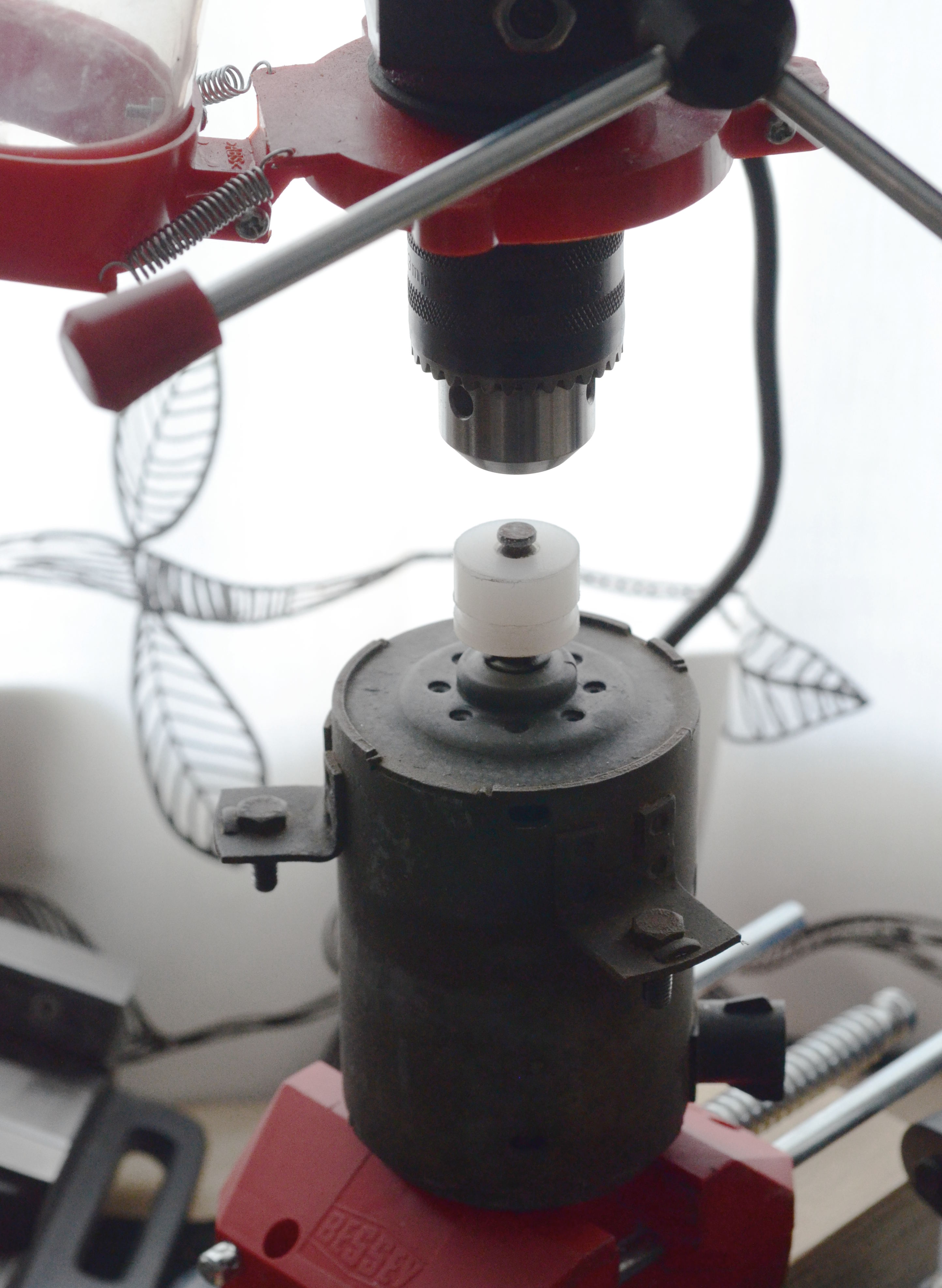
I saw someone, in a video or a post perhaps, saying they had made a plastic handle or handle cover for a handwheel crank and that they liked the feel of that. I had a fairly loose and awkward handle on the carriage, so I thought I'd try the same.
I took a leftover piece of PA6 that I had around from another project (brass hammer face). First I center drilled and drilled through to 3.5 mm that should clear the crank screw. I turned one end down to what felt like a reasonable large-ish diameter.
I then flipped the part and turned the other end to the outer diameter of a knob and made some progressive shoulders feeding both wheels by feel. I used a graver to smooth out and shape the end. It seems this isn't a very nice material and/or my technique isn't very good, but I still managed to safely smooth out a knob shape. I also measured out the old handle (20 mm) and the new (almost 35 mm) and drilled the difference as a recess for the screw head.
Now, I could test fit the handle. Turns out the Nylon rod bounces back even more than I expected and the screw doesn't clear the hole. I chucked the part again and drilled the hole out to 4 mm turning by hand. This made a nice fit without noticeable rattle, so I thought I'd stick with that. I needed to add one more washer to make sure the screw doesn't protrude from the nut at the back and hit the carriage. So I had drilled a bit deep, but that's hard to control and the recess isn't flat bottomed anyway. Easy enough fix, though.
The handle was deliberately left somewhat extra chunky, both long and fat. I can probably turn it down some more if I don't like the wheel or the old one can be swapped back in. It certainly feels nice turning the crank with it now, but I'll have to see how it fares when turning and when gripping the wheel instead of the handle. It is a bit easier to hit while turning the cross slide wheel than the slimmer handle was.
I could also probably turn a press-fit shell for the cross slide handle. So far I haven't really wanted to change that, though.
Dial indicator mount
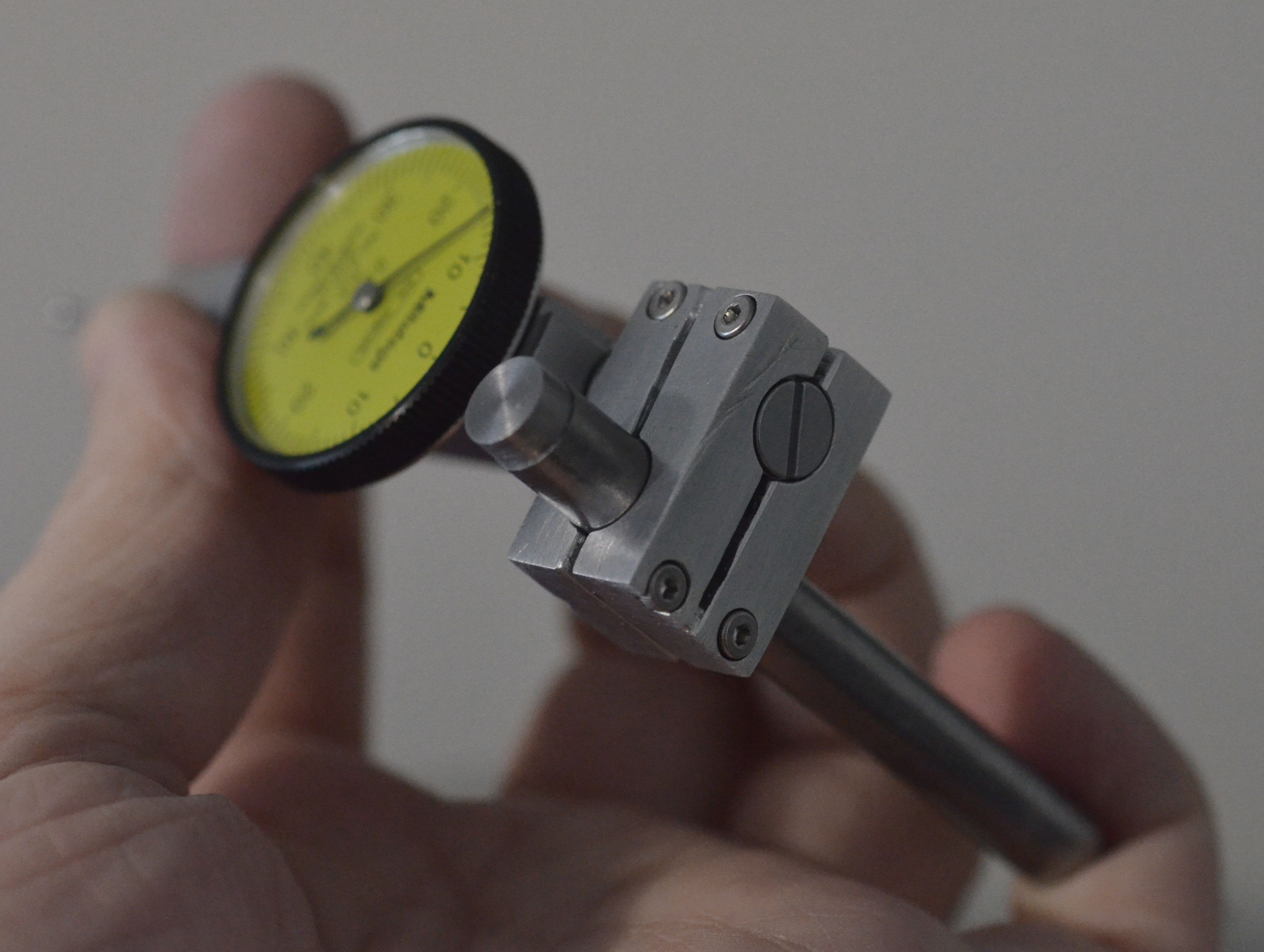
I have a shady DTI and I've wanted something to hold it in. I thought I'd turn a small block with holes in it for a post and the indicator screw.
It turned out to be a demonstration of how to fail at every turn. A learning experience, that is.
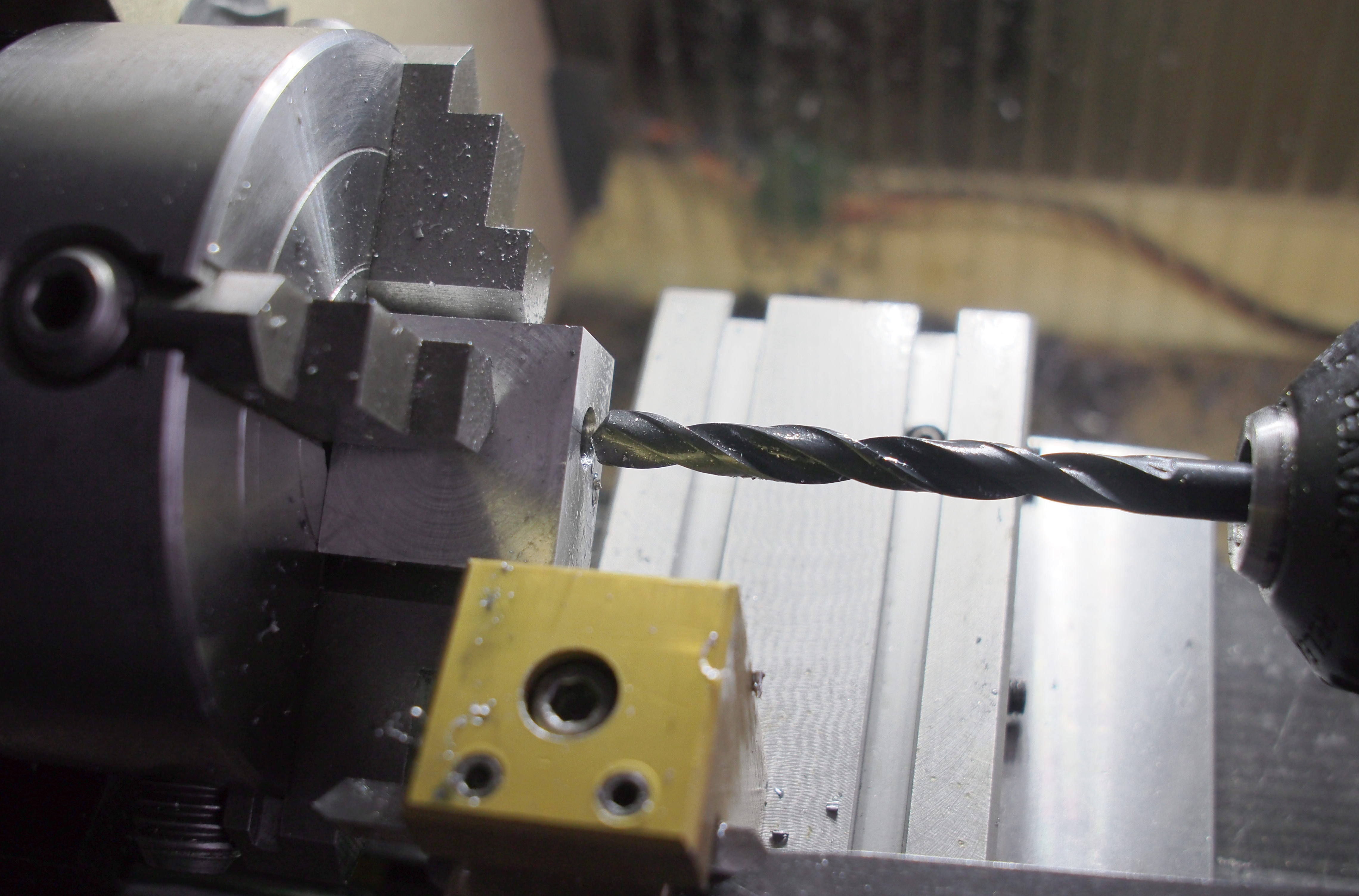
I cut up a piece of Al bar and cleaned up some of the sides. I thought I'd clean up later, but I didn't. Once more cuts are made, it becomes harder to make cuts and I get lazier, so only a bit of buffing ended up being done.
I drilled holes on the block on the lathe. Everything went fine until about 7.5 mm and especially 8 mm when the drill started binding strangely. Much like it would on nylon, but Al should not be a squishy material, so I couldn't figure out what the problem really was. My boring bar was not up to the task either, but eventually I managed to peck away a complete hole.
It would have needed to be oversize, but I had nothing easy at hand to cut a loose 8 mm hole. So, why not take another lesson opportunity, I thought and chucked up a piece of wood dowel. I turned the dowel into a fairly loose fit and put on some valve grinding paste, turned the revs way down and carefully inserted the piece on, prepared to let go if it got stuck.
The process worked out surprisingly well with coarse and fine (which really isn't) and the hole definitely ended up nicely oversize. I'm pretty sure a hole shaped this way especially in material this soft ends up an hourglass shape with a fairly coarse surface and hard to predict dimensions. But that works for me.
I hacksawed the usual clamping slots almost all the way through after very careful marking. Of course it wasn't straight or even, but it was functional. I had already noticed that there would be no room for clamping bolts larger than M2. D'oh!
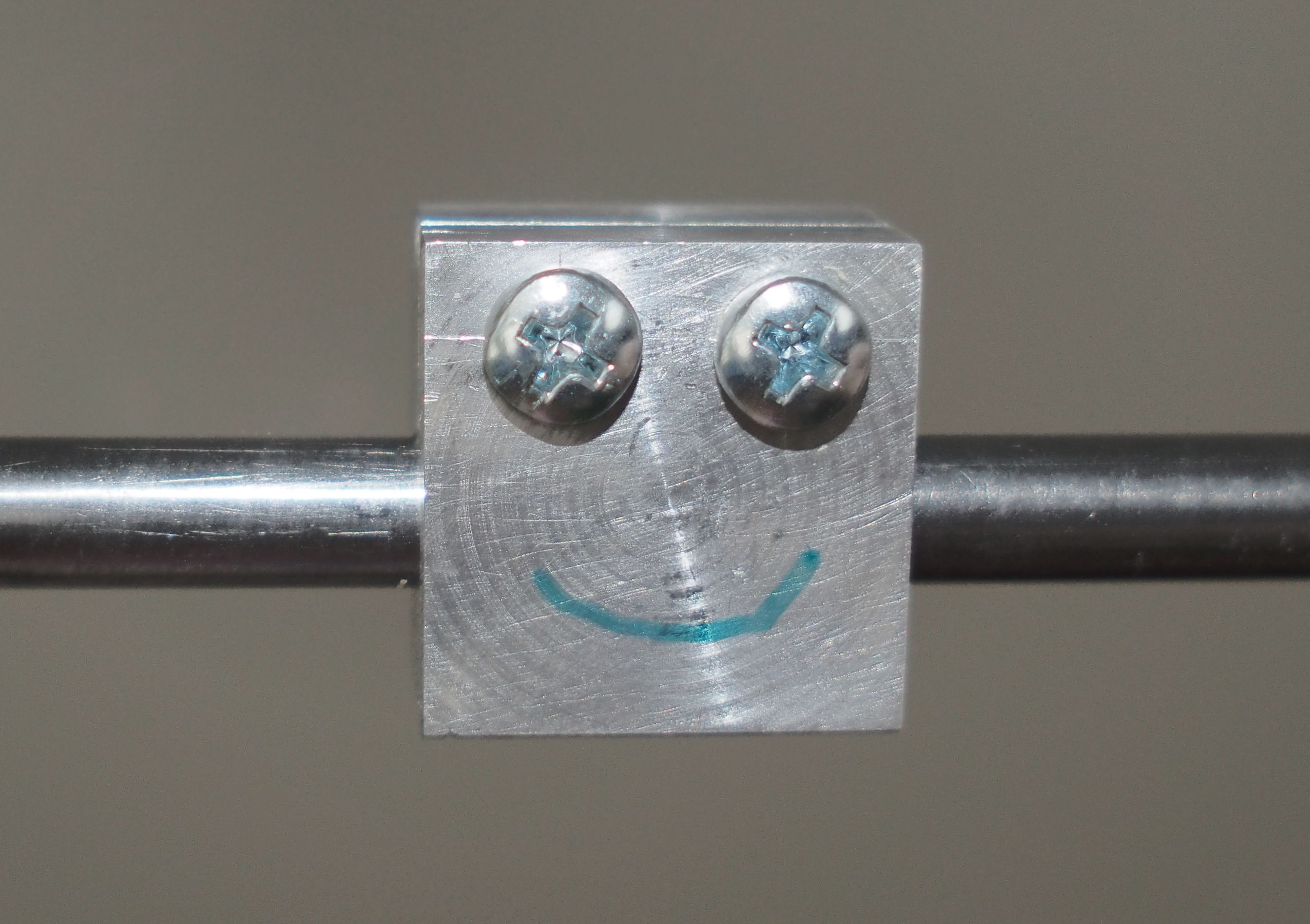
I very carefully scribed and punched myself a neat pattern for the holes and used a bench drill to drill through to 1.5 mm, halfway in to 2 mm, and a suitable depth counterbore (not proper, but functional) to fit the longest allen head M2 screws I had. Of course the holes were nowhere near where they were marked. I really must figure out how to stop my drill wandering that much. Maybe I need deeper punches or better work lighting.
I tapped the holes for M2 by hand, using the clearance side as a guide. The tap doesn't quite reach through the block, but neither will the screws. Otherwise the process worked out great and left very cute little clamping bolts almost where they were intended. Turns out, there's even enough clamping force on them with fairly easy torque to hold on to the indicator and a post (8 mm steel rod).
I'll have to see where to mount that and make the post or other bits so I can finally use the indicator some more. I should probably buy a plunger type one sometime. They're common and cheap enough.
I ended up sanding the sides and filing the slots a little round and finally buffed the surface with some steel wool. In the end it's not a hideous piece of metal despite the scars and scratches on the otherwise sort of satiny surface. And the lopsided bolt holes and crooked saw slots.
It's one more tool/jig I have now when I need it and the next one will be a little better again, I'm sure.
I've since checked and many of my drill bits including the 8 mm have serious wobble. I'll get some better quality ones. The power supply also seems to be the thing limiting my torque at the moment. I will keep an eye out for a stronger one.
The 8 mm hole also fits my dial indicator, though I'll probably be making a different one once I figure out where to mount it.
Flex coupling collars
I decided to try making a hose coupler for a brushless motor I have. Not too succesful. Perhaps too heavy and/or off-center while compressed. It could also be the hose, but esseantially there's a lot of vibration. This might still be useful with both shafts solidly held. Shelving the idea for now.
Links
- Main Taig page
- Taig tools
- Peatol (UK/EU dealer)