MIDI keyboard hacking
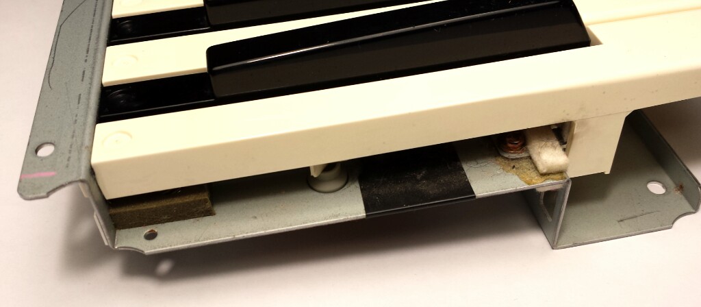
I took apart my hateful old Casio to scavenge the keybed. I've been intending to make a new scanner for it out of some microcontroller. UART based MIDI output and possibly sound generation will be goals. There may be wheels, sliders, inputs, buttons and things involved.
Parts and ideas
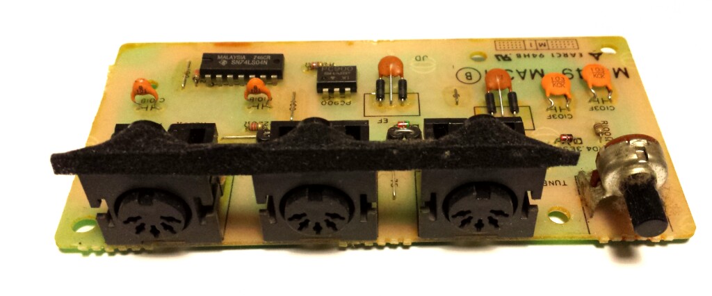
MIDI ports were actually on a daughtercard, so I also kept that. It has the required gate and opto connections for standard MIDI ports. I might like to have a more convenient connector if I'll have any more MIDI devices. RJ-11 4P4C seems tempting as it's easily available and reasonably easy to use.
Otherwise, any related MIDI parts and code could be used in other controller boxes etc, so it could all come in handy.
I'm could try to make some kind of a CAD model of the keybed for chassis dimensions. It would be a nice excuse to practice that process.
I'm also intending to connect it to a Monotron one way or another (CV, emulate strip, MIDI...). This should fix the "problems" in both: real keys and interesting sound output.
Keybed connections
I needed to map the electrical connections to the keybed. There are 17 pins that were connected with a soldered ribbon cable to the motherboard. The keybed has three boards on it, marked KY1M - KY3M, containing the pads for the key switches and diodes in sets of 6. It's a single layer board with 8 jumpers total (plus the diodes), so it's quite some spaghetti. It's still neatly grouped so I simply scribbled some diagrams in a notebook on what things are connected.
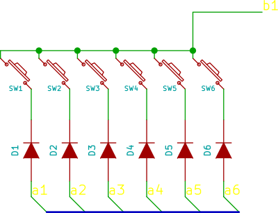
The key switches seem to be in groups of 6 with one end per group connected together and taken out. The other side goes through diodes do 6 nets that are connected in parallel. I called these groups a1-a6 and b1-b11. So it turns out it's an ordinary matrix of 6x11 (17) pins.
I expect a1-a6 have pull ups and inputs and b1-b11 groups are pulled down by the scanner so one group is read at a time. You could probably do key detection instead of continuous scan by reading the a1-a6 lines and waiting for 1 while holding b1-b11 high. When a key is detected, you scan with one b line high at a time.
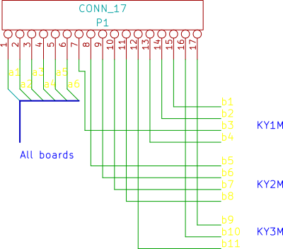
Since there are 61 keys in five octaves, there are 10 groups of 6 and one group (b9) with only one key (a1). The five blank spots could be used for other switches and more groups could be added for buttons. I'll have to see if that is practical. Scanning 8x16 should be natural. Debouncing that many switches might be interesting, though.
I drew up a little neater schematic, but it's incomplete. It should be enough to remember connections by. I haven't decided how I'll deal with the connector. I will probably have to duplicate the ribbon cable to the keybed and make a more solid card there to hold a connector in the other end. I'd rather not have a long tail soldered to the board. 17 (18/20/...) pin connectors should be common. I would have had 16 pins in single line with 2.54mm pitch. That would actually work if I sacrifice the top C :)
MIDI interfacing
I traced the MIDI card one day at Tarlab. Here's a plot of the schematic: SVG PNG. It really is almost a reference implementation. It should not be hard to connect it to an UART. There's also the tuning reference pot.
This means I should be able to power it on and feed MIDI from somewhere (Kurzweil) and see what comes out of the optoisolator. If it looks like UART traffic, I could plug in a logic analyser and feed it to sigrok.
MIDI is sent over a simple current loop at 31250 bps, 8N1 (by the byte). It's not a clock you usually find on 8250-style UARTS and thus probably not in USB uarts either. Microcontrollers can often be clocked to it if the clock sources divide neatly.
Increasingly, computers use special USB MIDI transport that is mostly almost entirely different. This will need more complex software/firmware support.
Firmware
I haven't made up my mind on what controller to use. I have several AVRs with hardware UARTs, so that seems a start. Stellaris/TIVA could be another option. It would certainly have more flexible clocking, lots of pins and other potential on-board including native USB. It might even have considerable potential as a sound generator. Similarly an STM32 board.
The MIDI daughtercard is probably designed for 5V so it might be easy to run the controller at that as well. Naturally, enough GPIO pins are needed and an ADC (for pots/wheels) could be useful.
Two ways to start digging. First is to probe an existing MIDI bus and see what it looks like using a scope and logic analyzer first. Then attach the daughtercard and see that it works. Then try to get an UART to send and/or receive MIDI commands. This would require hanging around a working MIDI out device such as my PC361.
Second way would be to start with key scanning and debouncing and output to LEDs or a beep generator. I have a keypad from an old phone that would be a compact start to that. Adding an arp would turn the mono beep into a way to confirm polyphonic scans. From here, you could wake up some ADCs and scan a modwheen and bend as well. This could be easily done anywhere.
Oh, my! Multistomp / libopencm3 has working USB MIDI for F103 and the project is even on a blue board!
Links
- USB MIDI spec
- Tutorialish AVR MIDI contorller article
- More tiny2313 MIDI and clocking notes
- DJB-MIDI contains tiny2313 inits and ideas
- Midi for CX-3 seems a somewhat similar project.
- MIDI and the AVR (pdf)
- V-USB-MIDI
- attiny45 MIDI
- Monotron MIDI
- ARP 3620
- LPC1114 Synthesizer
- Possible USB midi sources to look through (duino)
- Very tutorial-y MIDI sending (duino)
- MIDI clocks
- MBED USB MIDI Fascinating stuff here!
- Diykeyboard sources contain interesting stuff