Emco arrived
It's getting worse.

A few weeks ago now, I ran across an auction of one of these machines, in my hometown no less, 15 min drive away. And at the kind of prices I'd said I'd buy a complete watchmaker's lathe without blinking. I did blink a little before sending a message that I would like it and could pay and pick it up any time. I did pay and pick it up within the day.
This was a very complete or even overfurnished system that looks to be in excellent shape. I haven't yet used it much, but everything looks peachy.
It's a benchtop lathe, somewhere between the Unimat and Maximat ranges or so. The machine is marked, as these are, "Made in Austria by Maier+Co". I think these were made in 1970-80's range. Cast iron and steel construction and design much like bigger lathes. There's perhaps a serial number on the bed, but I don't have a dating source or decoding ideas.
Problems
Kein problem.
Well, one of the drill chucks has a fair bit of dried oil il in and another one seems stiff otherwise. All the T nut(s) is 12 mm while the slots are 8 mm. It's probably project material. There are square nuts and studs to use anyway.
One of the threading/feed gears has some stripped teeth but there's a replacement one, so the set is still probably complete.
Lathe motor temp test
Just a brief log. I noticed the emco motors can get quite hot.
16:17 23.8 C baseline, no runtime today.
16:26 32.6
16:32 44.0
16:37 47.4
16:40 48.6
17:00 48.4 Some measuring and run later
Degree a minute in active use, very broadly. This would mean half hour sessions at a time max. It is a very old motor and might need replacing some day. I should take it out, clean everything and measure the cap. There is no smell or any visible problem with it and it runs well.
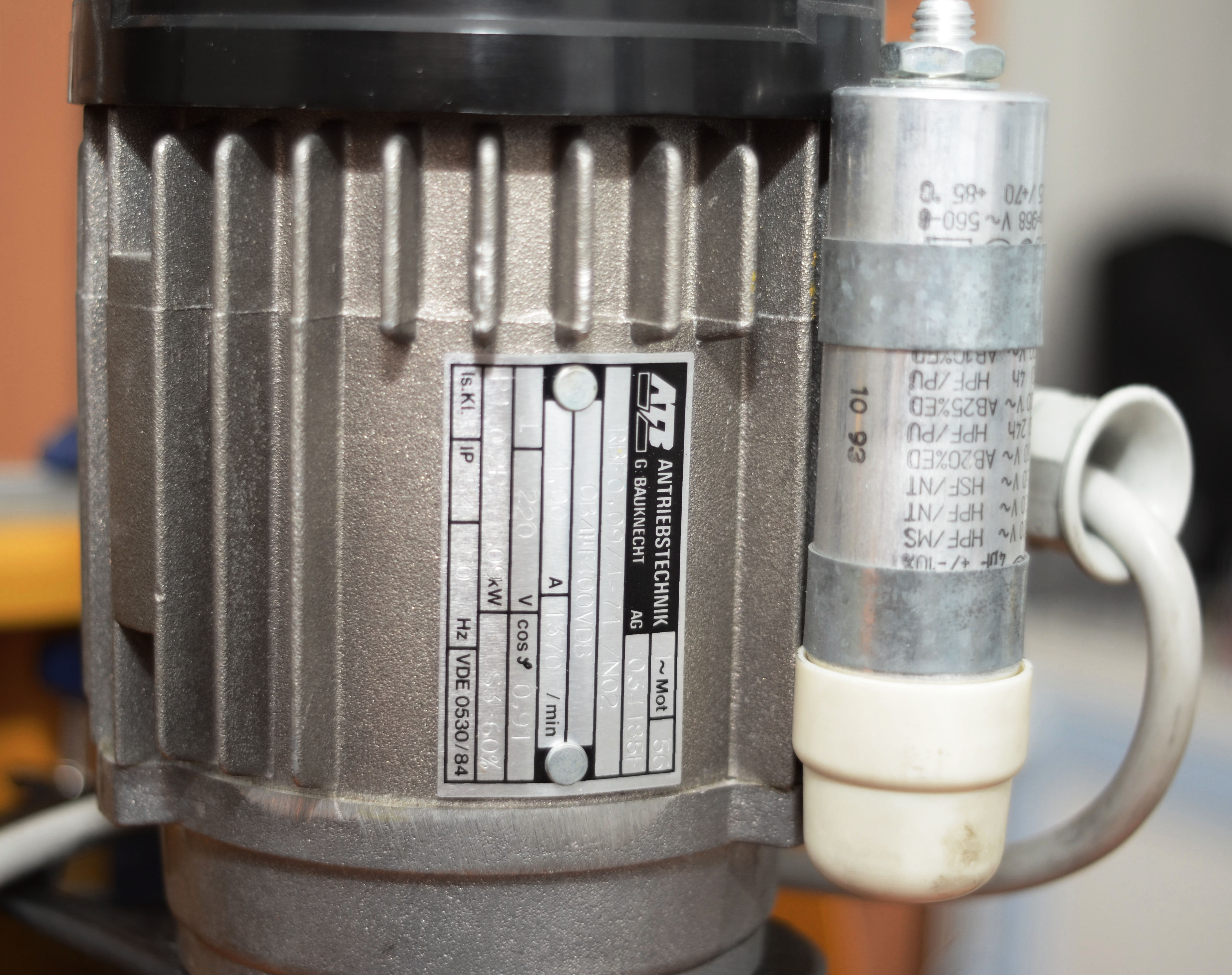
The manual says the motor has these stats:
Input power (P1) 500 W, S3-60%Output power (P2) at 2800 rpm 300W, S3-60%
And the milling head:
Input power (P1) 200 W, S3-60% IDOutput power (P2) 100W, S3-60% ID
So, that would mean it's a 200 W heater on the lathe and 100 W heater on the milling head. Seems pretty normal for non-continous power rating.
Projects
So far I've barely made a few cuts and holes. I can probably jump right in with this as soon as I next start to do something. I honed some of the tools and checked edges and did some CLA, taking apart the lathe chucks and wiping down ways and slides. I also tested the 2-way toolpost and looks like it needs some shims with the tools I have. I'll look into that. It's almost like having a few extra QCTP blocks for some special pair.
There are other machining projects of mine on the Taig page and in blog posts.
Threading test
I decided to try and make a 1/4" 20 TPI screw to practice threading. Why this size? Because it's very hard to find dies for the size. Perhaps also because Tarlab has a pile of nuts for it. Perhaps because it could be used to mount a camera.
Perhaps because it seemed like an annoying thread to make. I also picked an annoying material, cheap structural steel. I did actually botch the first attempt somehow. Maybe I did the advance twice by accident. Whatever the cause, the tool dug in, the work bent and slipped the center. I sawed it off and started over.
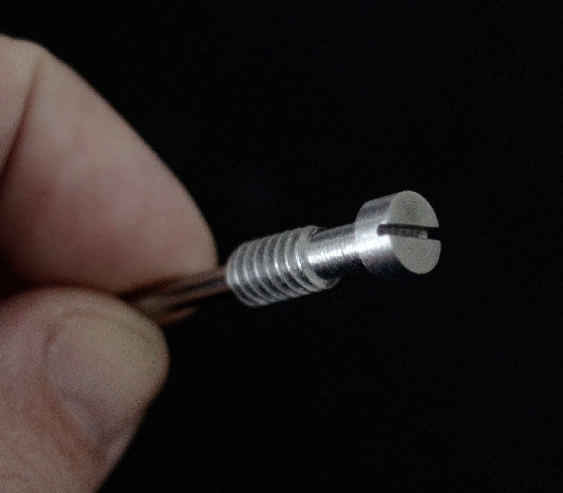
Like the first time, I did the threading using a hand crank because I didnt want the extra excitement of speed before I'd figured this all out. The second time worked out quite nice. Very rough finish, but it fits a camera and some other threads I have. I parted it off with a grooving tool and cleaned the head a bit and considered using a slitting saw or milling a hex head on, but instead just hacksawed in a slot. In hindsight, it's probably better to groove deep and hacksaw the bit off as the tool is fairly wide and the final parting is a bit unnecessarily violent and you end up having to clean the end anyway.
Latch
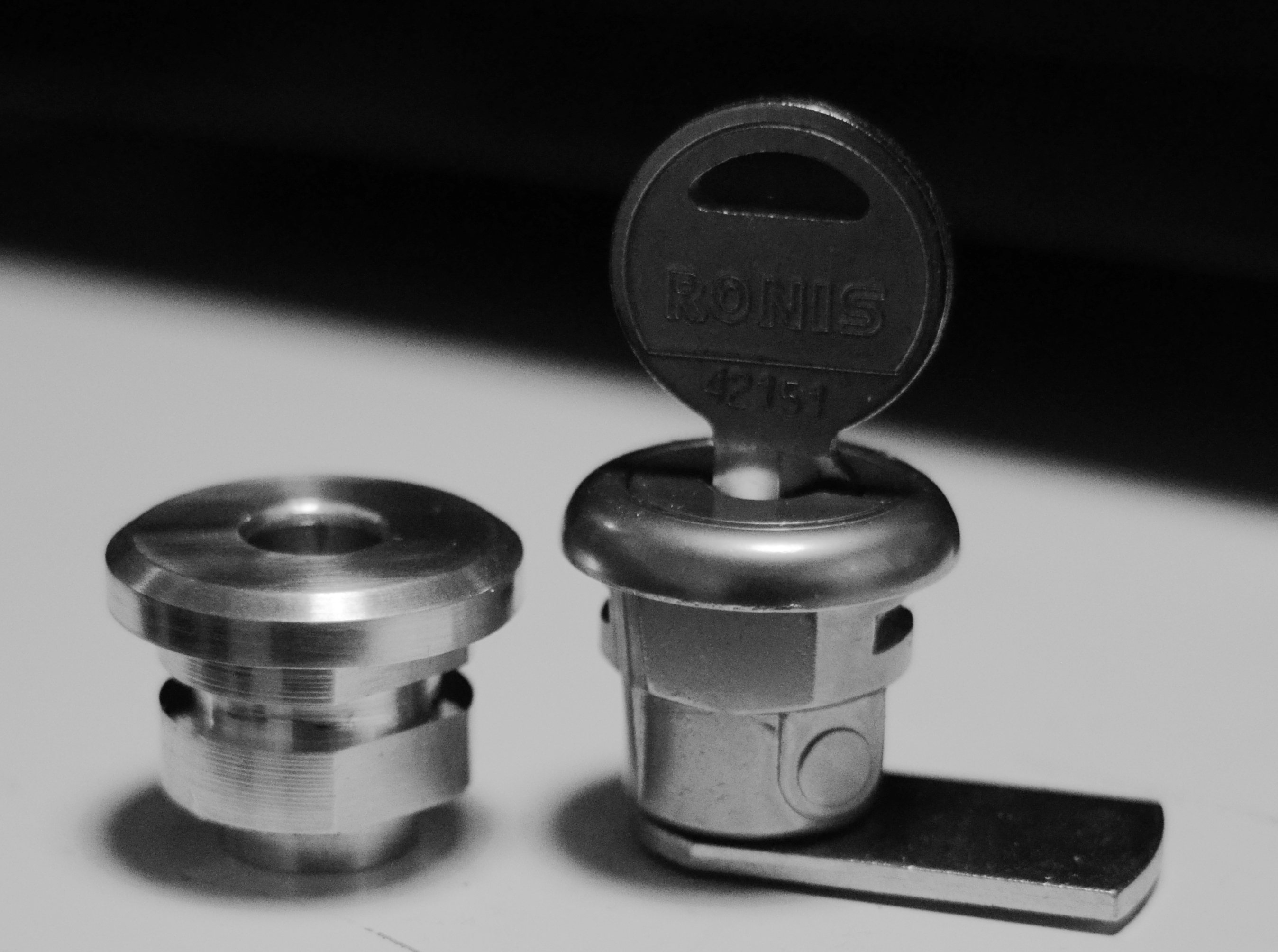
I installed a sort of a junction box that cars plug into in the winter as a part of a solar panel setup, but I'd rather not keep a lock on it because the key is bound to go missing eventually. So, I thought I would be able to replace it with a latch that can keep it closed and make it easy to open when needed.
This was the start of that. I drew up a model in FreeCAD first to figure out some dimensions. I picked out a chunk of Al scrap that would be big enough to make this part and hold on to it for the process. But then I thought I could just 3D print the part at Tarlab first to check the dimensions. The second box I have is somewhat damaged and doesn't close properly, so it will probably take some final fitting. Still, it was instructive.
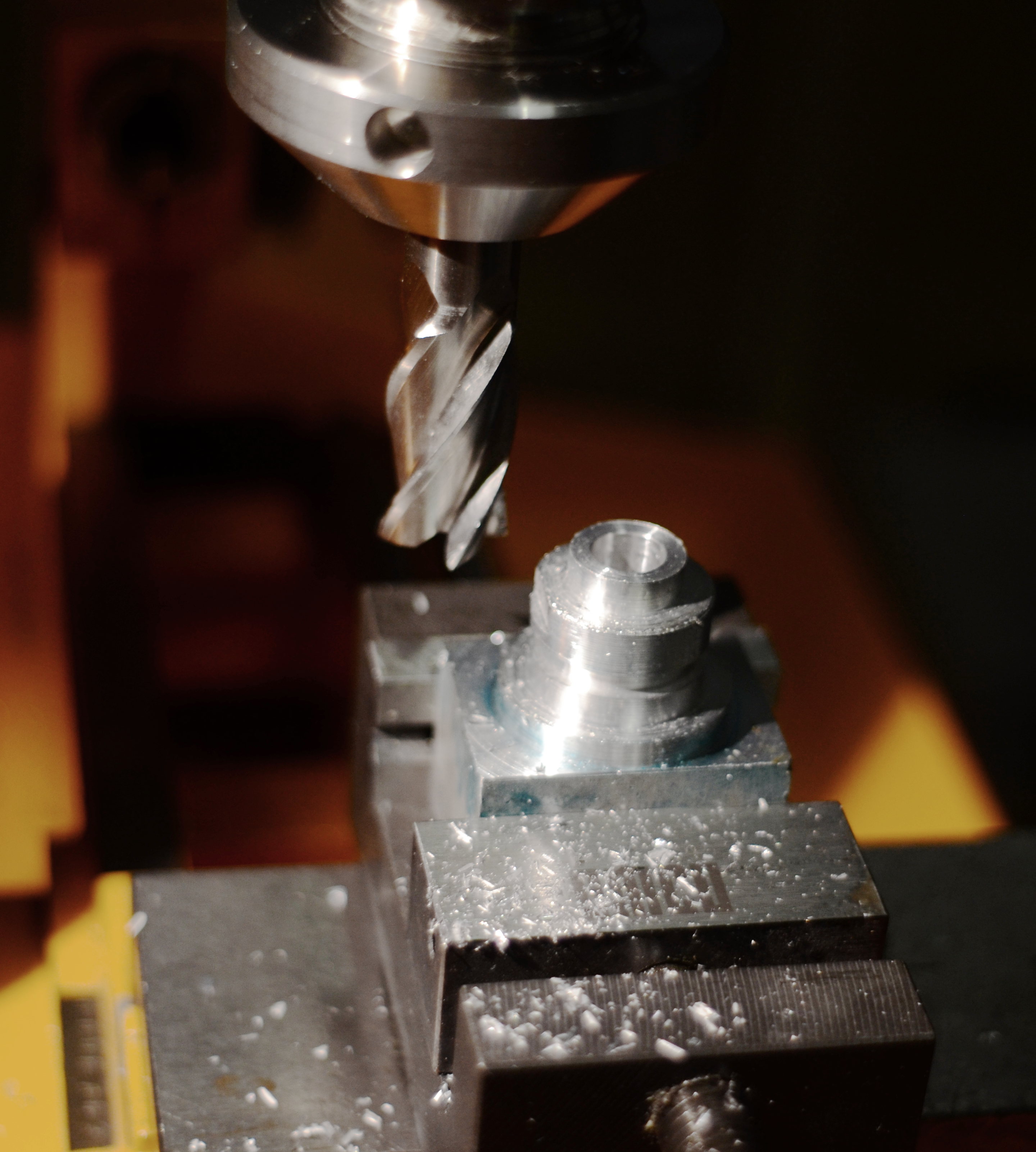
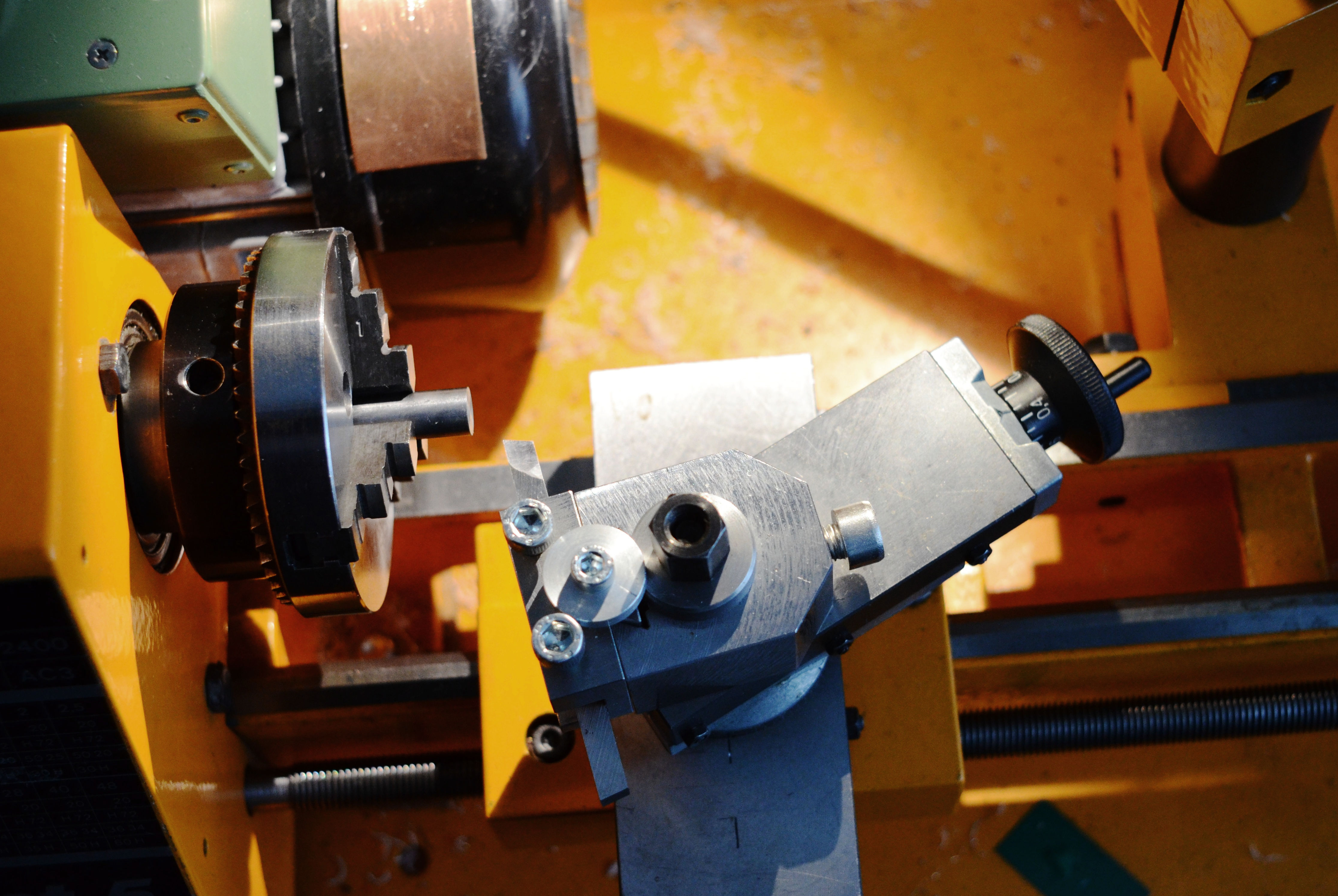
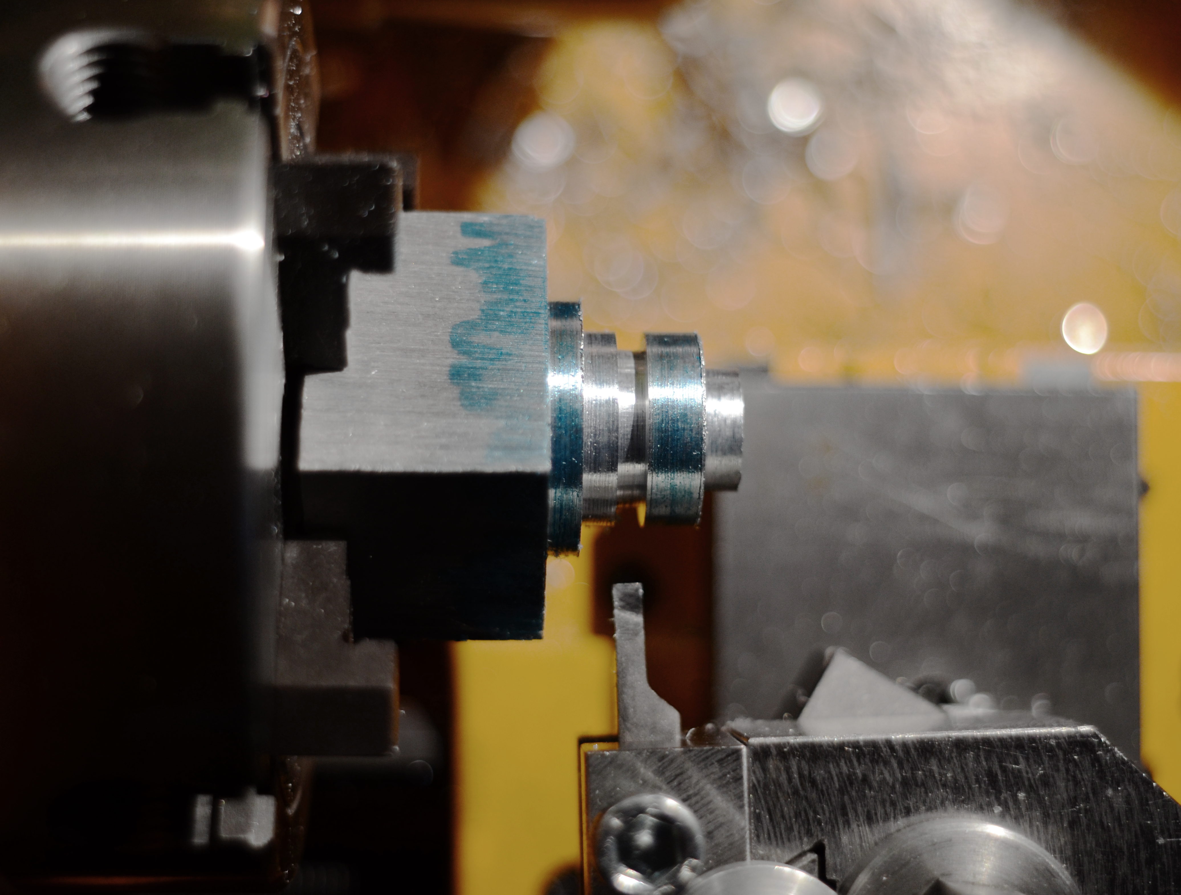
I used a four jaw to hold the piece and turned down the body and cut a (wide) groove for an E clip. I also drilled the part most of the depth to 7.5 mm. I then took the part out and moved it to the milling vise and cut flats that should mate with the box opening just like the lock barrel.
Finally, I sawed the part off and cleaned leftover piece. I mounted the part the other way in a three jaw chuck and cleaned and chamfered (yay for topslide) the surface. The I carefully drilled the hole open from the other side and determined that it was quite neatly centered with the previous hole. I reamed the hole to 8 mm all the way and tested on a shaft. That will probably work.
I will need to decide on the handle, spacer system and the latch proper and how they will install on site to a somewhat unknown box and not slip.
This may be one of the cutest parts I've ever made and certainly the most thorough and succesful mechanical drawings I've done. Well, I didn't bother with actual drawings this time as I usually only do that if I need templates. I just looked at the sketches for the model where the dimensional constraints are and used those as measurements for the part.